
Page 71 - Electric Machinery Fundamentals
P. 71
INTRODUCTION TO MACHINERY PRINCIPLES 47
200
180
160
140
~ 120
.f' 100
g
OJ
:> 80 -
60
r 40
20
0
0 5 10 IS 20 25 30 35 40 45 50
Force (N)
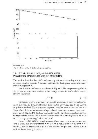
FIGURE 1- 28
Plot of velocity versus force for a linear de machine.
1.9 REAL, REACTIVE, AND APPARENT
POWER IN SINGLE-PHASE AC CIRCUITS
This section describes the relationships among real, reactive, and apparent power
in single-phase ac circuits. A similar discussion for three-phase ac circuits can be
found in Appendix A.
In a de circuit such as the one shown in Figure 1-29a, the power supplied to
the dc load is simply the product of the voltage across the load and the current
flowing through it.
p ~ VI (I-55)
Unfortunately, the situation in sinusoidal ac circuits is more complex, be-
cause there can be a phase difference between the ac voltage and the ac current
supplied to the load. The instantaneous power supplied to an ac load will still be
the product of the instantaneous voltage and the instantaneous current, but the av-
erage power supplied to the load will be affected by the phase angle between the
voltage and the current. We will now explore the effects of this phase difference
on the average power supplied to an ac load.
Figure 1- 29b shows a single~phase voltage source supplying power to a
single-phase load with impedance Z ~ ZLe n. If we assume that the load is in-
ductive, then the impedance angle e of the load will be positive, and the current
will lag the voltage by e degrees.