
Page 67 - Electric Machinery Fundamentals
P. 67
INTRODUCTION TO MACHINERY PRINCIPLES 43
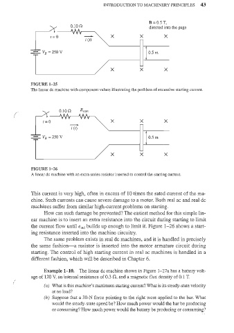
r o O.lOn i (r) X X B = 0.5 T,
directed into the page
X
-=- VB =250V 0.5 m
X X X
FIGURE 1- 25
The linear de machine with component values illustrating the problem of excessive starting current.
fo X X X
( 0.10 n Rstart
; (t)
-=- VB =250V 0.5 m
X X X
FIGURE 1-26
A linear de machine with an extra series resistor inserted to control the starting current.
This current is very high, often in excess of 10 times the rated current of the ma-
chine. Such currents can cause severe damage to a motor. Both real ac and real de
machines suffer from similar high-current problems on starting.
How can such damage be prevented? The easiest method for this simple lin-
ear machine is to inselt an extra resistance into the circuit during starting to limit
the current flow until eind builds up enough to limit it. Figure 1- 26 shows a start-
ing resistance inserted into the machine circuitry.
The same problem exists in real dc machines, and it is handled in precisely
the same fashion-a resistor is inserted into the motor armature circuit during
starting. The control of high starting current in real ac machines is handled in a
different fashion, which will be described in Chapter 6.
Example 1- 10. The linear dc machine shown in Figure 1-27a has a battery volt-
age of 120 V, an internal resistance of 0.3 fl, and a magnetic flux density of 0.1 T.
(
(a) What is this machine's maximum starting current? What is its steady-state velocity
at no load?
(b) Suppose that a 30-N force pointing to the right were applied to the bar. What
would the steady-state speed be? How much power would the bar be producing
or consuming? How much power would the battery be producing or consuming?