
Page 65 - Electric Machinery Fundamentals
P. 65
INTRODUCTION TO MACHINERY PRINCIPLES 41
R
B
X X X
i (I)
+ F llpp
F ind e ind -- ,.
X X X
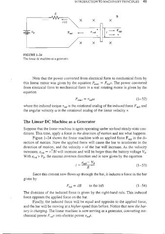
FIGURE 1-24
The linear de machine as a generator.
( Note that the power converted from electrical form to mechanical form by
this linear motor was given by the equation Peony = Fjndv. The power cOllverted
from electrical form to mechanical form in a real rotating motor is given by the
equation
(1-52)
where the induced torque Tind is the rotational analog of the induced force F ind. and
the angular velocity w is the rotational analog of the linear velocity v.
The Linear DC Machine as a Generator
Suppose that the linear machine is again operating under no-load steady-state con-
ditions. This time, apply a force in the direction a/motion and see what happens.
Figure 1- 24 shows the linear machine with an applied force F"p in the di-
rection of motion. Now the applied force will cause the bar to accelerate in the
direction of motion, and the velocity v of the bar will increase. As the velocity
increases, eind = vlSt will increase and will be larger than the battery voltage VB'
With eind > VI]' the current reverses direction and is now given by the equation
(1-53)
Since this current now flows up through the bar, it induces a force in the bar
given by
Find = ilB to the left (1- 54)
The direction of the induced force is given by the right-hand rule. This induced
( force opposes the applied force on the bar.
Finally, the induced force will be equal and opposite to the applied force,
and the bar will be moving at a higher speed than before. Notice that now the bat-
tery is charging. The linear machine is now serving as a generator, converting me-
chanical power FindV into electric power eindi.