
Page 73 - Electric Machinery Fundamentals
P. 73
INTRODUCTION TO MACH INERY PRINCIPLES 49
p(t)
Component 1
/
, , ,
I I
( 0.0 L--='----i-'--V---4----''f--+-'---'\'---7'----
o 12 I WI
I I
\
I
\
\ I \ I
"
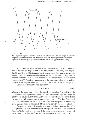
FIGURE 1-30
The components of power supplied to a single-phase load versus time. The first component represents
the power supplied by the component of current ill phase with the voltage, while the second term
represents the power supplied by the component of current 90° oul of phase with the voltage.
Note that the second term of the jnstantaneOlls power expression is positive
half of the time and negative half of the time, so that the average power supplied
by this term is zero. This term represents power that is first transferred from the
source to the load, and then returned from the load to the source. The power that
continually bounces back and forth between the source and the load is known as re-
active power (Q). Reactive power represents the energy that is first stored and then
released in the magnetic field of an inductor, or in the electric field of a capacitor.
The reactive power of a load is given by
Q=VJsinB (1- 61)
where e is the impedance angle of the load. By convention, Q is positive for in-
ductive loads and negative for capacitive loads, because the impedance angle e is
positive for inductive loads and negative for capacitive loads. The units of reac-
tive power are volt-amperes reactive (var), where I var = I V X 1 A. Even though
the dimensional units are the same as for watts, reactive power is traditionally
given a unique name to distinguish it from power actually supplied to a load.
The apparent power (S) supplied to a load is defined as the product of the
voltage across the load and the current through the load. This is the power that
"appears" to be supplied to the load if the pbase augle differences between volt-
age and CUlTent are ignored. Therefore, the apparent power of a 19ad is given by