
Page 75 - Electric Machinery Fundamentals
P. 75
INTRODUCTION TO MACl-llNERY PIUNCIPLES 51
Q+
v z z~ Izl Lon
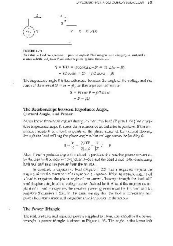
FIGURE 1-31
An inductive load has a positive impedance angle O. This load produces a lagging current, and it
consumes both real power P and reactive power Q from the source.
S = VI* = (V L ex)(l L -f3) = VI L(<> - f3)
= VI cos(<> - f3) + jVI sin(ex - f3)
The impedance angle 8 is the difference between the angle of the voltage and the
angle ofthe current (8 = <> - f3), so this equation reduces to
S = VI cos 8 + jVI sin 8
=p + jQ
The Relationships between Impedance Angle,
Cnrrent Angle, and Power
As we know from basic circuit theory, an inductive load (Figure 1- 31) has a pos-
itive impedance angle e, since the reactance of an inductor is positive. If the im-
pedance angle f) of a load is positive, the phase angle of the current flowing
through the load will lag the phase angle of the voltage across the load by 8.
I=~= VLoo= .1'.- L_8
Z IZILe Izl
Also, if the impedance angle f) of a load is positive, the reactive power consumed
by the load will be positive (Equation 1-65), and the load is said to be consuming
both real and reactive power from the source.
In contrast, a capacitive load (Figure 1-32) has a negative impedance
angle e, since the reactance of a capacitor is negative, If the impedance angle e of
a load is negative, the phase angle of the current flowing through the load will
lead the phase angle of the voltage across the load by 8. Also, if the impedance an-
gle 8 of a load is negative, the reactive power Q consumed by the load will be
negative (Equation 1-65). In this case, we say that the load is consuming real
power from the source and supplying reactive power to the source.
The Power Triangle
The real, reactive, and apparent powers supplied to a load are related by the power
triangle. A power triangle is shown in Figure 1- 33. The angle in the lower left