
Page 142 - Electrical Equipment Handbook _ Troubleshooting and Maintenance
P. 142
SPEED CONTROL OF INDUCTION MOTORS
SPEED CONTROL OF INDUCTION MOTORS 7.9
4. Power factor
5. Speed
6. Nominal efficiency
7. NEMA design class
8. Starting code
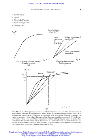
FIGURE 7.9 (a) The magnetization curve of an induction machine. It is a plot of the terminal voltage of
the machine as a function of its magnetization current (which lags the phase voltage by approximately 90°).
(b) Plot of the voltage-current characteristic of a capacitor bank. Note that the larger the capacitance, the
greater its current for a given voltage. This current leads the phase voltage by approximately 90°. (c) The no-
load terminal voltage for an isolated induction generator can be found by plotting the generator terminal char-
acteristic and the capacitor voltage-current characteristic on a single set of axes. The intersection of the two
curves is the point at which the reactive power demanded by the generator is exactly supplied by the capacitors,
and this point gives the no-load terminal voltage of the generator.
Downloaded from Digital Engineering Library @ McGraw-Hill (www.digitalengineeringlibrary.com)
Copyright © 2004 The McGraw-Hill Companies. All rights reserved.
Any use is subject to the Terms of Use as given at the website.