
Page 141 - Electrical Equipment Handbook _ Troubleshooting and Maintenance
P. 141
SPEED CONTROL OF INDUCTION MOTORS
7.8 CHAPTER SEVEN
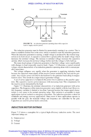
FIGURE 7.8 An induction generator operating alone with a capacitor
bank to supply reactive power.
The induction generator must be flashed by momentarily running it as a motor. This is
done to establish residual flux in the rotor, which is needed to start the induction generator.
When the induction generator is starting, a small voltage is produced by the residual mag-
netism in its field circuit. A capacitive current flow is produced by the small voltage which
increases the terminal voltage. The increase in terminal voltage increases the capacitive
current, which increases the terminal voltage further until the voltage is fully built up.
The main disadvantage of induction generators is that their voltage varies significantly
with changes in load (especially reactive load). Figure 7.10 illustrates a typical terminal
voltage-current characteristic of an induction generator operating alone with a constant par-
allel capacitance.
The voltage collapses very rapidly when the generator is supplying inductive loads
because the capacitors must supply all the reactive power needed by the load and the gen-
erator. Any reactive power diverted to the load moves the generator back along its magne-
tization curve. This results in a major drop in generator voltage.
A set of series capacitors is included in the power line in addition to the parallel capac-
itors. The capacitive reactive power increases with increasing load. This compensates for
the reactive power demanded by the load.
Figure 7.11 illustrates the terminal characteristic of an induction generator with series
capacitors. The frequency of the induction generator varies slightly with the load. However,
this frequency variation is limited to less than 5 percent because the torque-speed charac-
teristic is very steep in the normal operating range. This variation is acceptable in many
applications such as isolated or emergency generators. The induction generator is ideal for
windmills and energy recovery applications. Since most of these applications operate in
parallel with the grid, the terminal voltage and frequency are controlled by the grid.
Capacitors are used for power factor correction.
INDUCTION MOTOR RATINGS
Figure 7.12 shows a nameplate for a typical high-efficiency induction motor. The most
important ratings are
1. Output power
2. Voltage
3. Current
Downloaded from Digital Engineering Library @ McGraw-Hill (www.digitalengineeringlibrary.com)
Copyright © 2004 The McGraw-Hill Companies. All rights reserved.
Any use is subject to the Terms of Use as given at the website.