
Page 140 - Electrical Equipment Handbook _ Troubleshooting and Maintenance
P. 140
SPEED CONTROL OF INDUCTION MOTORS
SPEED CONTROL OF INDUCTION MOTORS 7.7
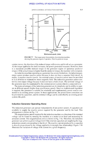
FIGURE 7.7 The torque-speed characteristic of an induction machine,
showing the generator region of operation. Note the pushover torque.
a prime mover, the direction of the induced torque will reverse and it will act as a generator.
As the torque applied to the shaft increases, the power generated increases. However, there
is a maximum possible induced torque in the generator region of operation (pushover
torque). If the actual torque is higher than the pushover torque, the machine will overspeed.
An induction machine operating as a generator has severe limitations. An induction gen-
erator cannot produce reactive power because it does not have a separate field circuit. In
reality, it requires reactive power. An external source of reactive power must be provided
to it at all times to maintain its stator magnetic field. The induction generator cannot con-
trol its own output voltage because it does not have a field circuit. The terminal voltage of
the generator must be maintained by the external power system which is connected to it.
The main advantages of the induction generator are its simplicity and its ability to oper-
ate at different speeds (higher than synchronous speed). Since no sophisticated regulation
is required, this generator is suitable for windmills and supplementary power sources con-
nected to an existing power system. In these applications, the power factor correction can
be provided by capacitors, and the terminal voltage can be controlled by an existing power
system (the grid).
Induction Generator Operating Alone
The induction generator can operate independently of any power system, if capacitors are
available to supply the reactive power required by the generator and by the load. This
arrangement is shown in Fig. 7.8.
The magnetization current required by the induction machine as a function of the terminal
voltage can be found by running the machine as a motor at no load and measuring its
armature current. This magnetization curve is shown in Fig. 7.9a. Therefore, the induction
generator can achieve a given voltage level if the external capacitors are supplying the mag-
netization current corresponding to that level. The reactive current produced by a capacitor
is directly proportional to the voltage applied to it (straight-line relationship). Figure 7.9b
illustrates the variation of voltage with current for a given frequency.
Downloaded from Digital Engineering Library @ McGraw-Hill (www.digitalengineeringlibrary.com)
Copyright © 2004 The McGraw-Hill Companies. All rights reserved.
Any use is subject to the Terms of Use as given at the website.