
Page 138 - Electrical Equipment Handbook _ Troubleshooting and Maintenance
P. 138
SPEED CONTROL OF INDUCTION MOTORS
SPEED CONTROL OF INDUCTION MOTORS 7.5
SPEED CONTROL BY CHANGING THE
ROTOR RESISTANCE
The shape of the torque-speed curve of wound rotor induction motors can be changed by
inserting extra resistances into the rotor circuit, as shown in Fig. 7.3. However, inserting
additional resistances into the rotor circuit will reduce the efficiency of the motor signifi-
cantly. This method is usually used for short periods.
SOLID-STATE INDUCTION MOTOR DRIVES
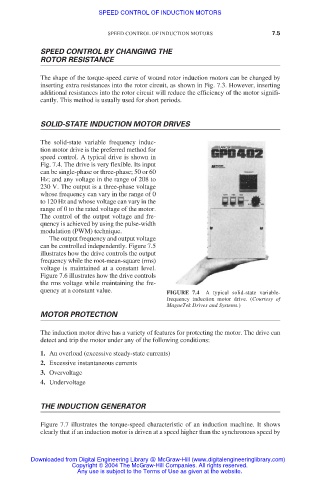
The solid-state variable frequency induc-
tion motor drive is the preferred method for
speed control. A typical drive is shown in
Fig. 7.4. The drive is very flexible. Its input
can be single-phase or three-phase; 50 or 60
Hz; and any voltage in the range of 208 to
230 V. The output is a three-phase voltage
whose frequency can vary in the range of 0
to 120 Hz and whose voltage can vary in the
range of 0 to the rated voltage of the motor.
The control of the output voltage and fre-
quency is achieved by using the pulse-width
modulation (PWM) technique.
The output frequency and output voltage
can be controlled independently. Figure 7.5
illustrates how the drive controls the output
frequency while the root-mean-square (rms)
voltage is maintained at a constant level.
Figure 7.6 illustrates how the drive controls
the rms voltage while maintaining the fre-
quency at a constant value. FIGURE 7.4 A typical solid-state variable-
frequency induction motor drive. (Courtesy of
MagneTek Drives and Systems.)
MOTOR PROTECTION
The induction motor drive has a variety of features for protecting the motor. The drive can
detect and trip the motor under any of the following conditions:
1. An overload (excessive steady-state currents)
2. Excessive instantaneous currents
3. Overvoltage
4. Undervoltage
THE INDUCTION GENERATOR
Figure 7.7 illustrates the torque-speed characteristic of an induction machine. It shows
clearly that if an induction motor is driven at a speed higher than the synchronous speed by
Downloaded from Digital Engineering Library @ McGraw-Hill (www.digitalengineeringlibrary.com)
Copyright © 2004 The McGraw-Hill Companies. All rights reserved.
Any use is subject to the Terms of Use as given at the website.