
Page 163 - Electrical Equipment Handbook _ Troubleshooting and Maintenance
P. 163
MAINTENANCE OF MOTORS
8.18 CHAPTER EIGHT
Large and medium-size high-speed motors are the most susceptible to cracks in the
cage winding. Large, low-speed motors driving high-inertia loads such as induced-draft
(ID) and forced-draft (FD) boiler fans are also susceptible to this mode of failure. The bar
extensions, short-circuit rings, and joints between these components are most susceptible
to cracking. Cyclic mechanical stresses occurring during start-up lead to cracking by
fatigue failure. These stresses are mainly produced by centrifugal forces and differential
thermal expansion.
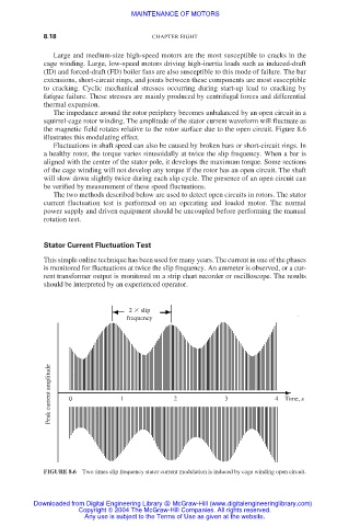
The impedance around the rotor periphery becomes unbalanced by an open circuit in a
squirrel-cage rotor winding. The amplitude of the stator current waveform will fluctuate as
the magnetic field rotates relative to the rotor surface due to the open circuit. Figure 8.6
illustrates this modulating effect.
Fluctuations in shaft speed can also be caused by broken bars or short-circuit rings. In
a healthy rotor, the torque varies sinusoidally at twice the slip frequency. When a bar is
aligned with the center of the stator pole, it develops the maximum torque. Some sections
of the cage winding will not develop any torque if the rotor has an open circuit. The shaft
will slow down slightly twice during each slip cycle. The presence of an open circuit can
be verified by measurement of these speed fluctuations.
The two methods described below are used to detect open circuits in rotors. The stator
current fluctuation test is performed on an operating and loaded motor. The normal
power supply and driven equipment should be uncoupled before performing the manual
rotation test.
Stator Current Fluctuation Test
This simple online technique has been used for many years. The current in one of the phases
is monitored for fluctuations at twice the slip frequency. An ammeter is observed, or a cur-
rent transformer output is monitored on a strip chart recorder or oscilloscope. The results
should be interpreted by an experienced operator.
2
slip
frequency
Peak current amplitude 0 1 2 3 4 Time, s
FIGURE 8.6 Two times slip frequency stator current modulation is induced by cage winding open circuit.
Downloaded from Digital Engineering Library @ McGraw-Hill (www.digitalengineeringlibrary.com)
Copyright © 2004 The McGraw-Hill Companies. All rights reserved.
Any use is subject to the Terms of Use as given at the website.