
Page 159 - Electrical Equipment Handbook _ Troubleshooting and Maintenance
P. 159
MAINTENANCE OF MOTORS
8.14 CHAPTER EIGHT
voltage that the insulation of the motor can withstand. The voltage reached during these tests
is much higher than the voltage recommended for the nondestructive dc high-potential
test. They are performed by a qualified operator to prevent the destruction of the motor.
Surge Testing
The dc high-potential test confirms the integrity of the insulation. However, it does not
indicate a failure of the insulation between the turns of the windings (interturn fault). The
surge test is used to detect the early stages of insulation failures in the windings such as
coil-to-coil failures, short circuits, ground, and misconnections. During the surge test, brief
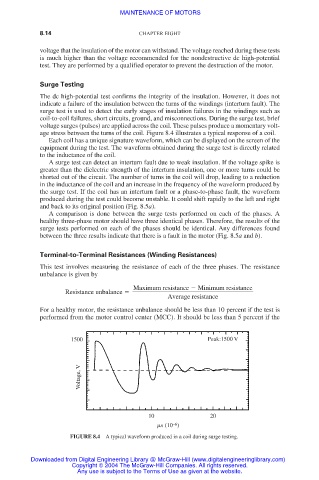
voltage surges (pulses) are applied across the coil. These pulses produce a momentary volt-
age stress between the turns of the coil. Figure 8.4 illustrates a typical response of a coil.
Each coil has a unique signature waveform, which can be displayed on the screen of the
equipment during the test. The waveform obtained during the surge test is directly related
to the inductance of the coil.
A surge test can detect an interturn fault due to weak insulation. If the voltage spike is
greater than the dielectric strength of the interturn insulation, one or more turns could be
shorted out of the circuit. The number of turns in the coil will drop, leading to a reduction
in the inductance of the coil and an increase in the frequency of the waveform produced by
the surge test. If the coil has an interturn fault or a phase-to-phase fault, the waveform
produced during the test could become unstable. It could shift rapidly to the left and right
and back to its original position (Fig. 8.5a).
A comparison is done between the surge tests performed on each of the phases. A
healthy three-phase motor should have three identical phases. Therefore, the results of the
surge tests performed on each of the phases should be identical. Any differences found
between the three results indicate that there is a fault in the motor (Fig. 8.5a and b).
Terminal-to-Terminal Resistances (Winding Resistances)
This test involves measuring the resistance of each of the three phases. The resistance
unbalance is given by
Maximum resistance Minimum resistance
Resistance unbalance
Average resistance
For a healthy motor, the resistance unbalance should be less than 10 percent if the test is
performed from the motor control center (MCC). It should be less than 5 percent if the
1500 Peak:1500 V
Voltage, V
10 20
–6
s (10 )
FIGURE 8.4 A typical waveform produced in a coil during surge testing.
Downloaded from Digital Engineering Library @ McGraw-Hill (www.digitalengineeringlibrary.com)
Copyright © 2004 The McGraw-Hill Companies. All rights reserved.
Any use is subject to the Terms of Use as given at the website.