
Page 242 - Electrical Equipment Handbook _ Troubleshooting and Maintenance
P. 242
SYNCHRONOUS GENERATORS
SYNCHRONOUS GENERATORS 12.5
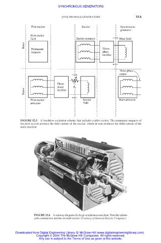
FIGURE 12.5 A brushless excitation scheme that includes a pilot exciter. The permanent magnets of
the pilot exciter produce the field current of the exciter, which in turn produces the field current of the
main machine.
FIGURE 12.6 A cutaway diagram of a large synchronous machine. Note the salient-
pole construction and the on-shaft exciter. (Courtesy of General Electric Company.)
Downloaded from Digital Engineering Library @ McGraw-Hill (www.digitalengineeringlibrary.com)
Copyright © 2004 The McGraw-Hill Companies. All rights reserved.
Any use is subject to the Terms of Use as given at the website.