
Page 244 - Electrical Equipment Handbook _ Troubleshooting and Maintenance
P. 244
SYNCHRONOUS GENERATORS
SYNCHRONOUS GENERATORS 12.7
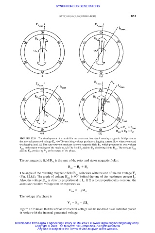
FIGURE 12.8 The development of a model for armature reaction: (a) A rotating magnetic field produces
the internal generated voltage E . (b) The resulting voltage produces a lagging current flow when connected
A
to a lagging load. (c) The stator current produces its own magnetic field B , which produces its own voltage
S
E in the stator windings of the machine. (d) The field B adds to B , distorting it into B . The voltage E
stat S R net stat
adds to E , producing V at the output of the phase.
A
The net magnetic field B is the sum of the rotor and stator magnetic fields:
net
B B B
net R S
The angle of the resulting magnetic field B net coincides with the one of the net voltage V
(Fig. 12.8d). The angle of voltage E stat is 90° behind the one of the maximum current I .
A
Also, the voltage E stat is directly proportional to I . If X is the proportionality constant, the
A
armature reaction voltage can be expressed as
E jXI
stat A
The voltage of a phase is
V E jXI
A A
Figure 12.9 shows that the armature reaction voltage can be modeled as an inductor placed
in series with the internal generated voltage.
Downloaded from Digital Engineering Library @ McGraw-Hill (www.digitalengineeringlibrary.com)
Copyright © 2004 The McGraw-Hill Companies. All rights reserved.
Any use is subject to the Terms of Use as given at the website.