
Page 243 - Electrical Equipment Handbook _ Troubleshooting and Maintenance
P. 243
SYNCHRONOUS GENERATORS
12.6 CHAPTER TWELVE
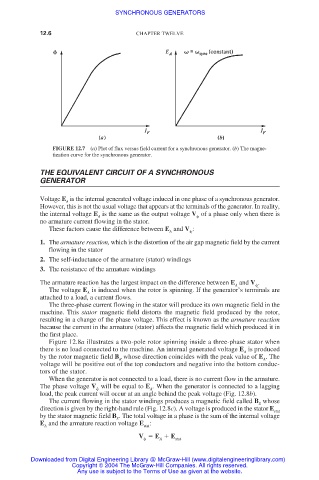
FIGURE 12.7 (a) Plot of flux versus field current for a synchronous generator. (b) The magne-
tization curve for the synchronous generator.
THE EQUIVALENT CIRCUIT OF A SYNCHRONOUS
GENERATOR
Voltage E is the internal generated voltage induced in one phase of a synchronous generator.
A
However, this is not the usual voltage that appears at the terminals of the generator. In reality,
the internal voltage E is the same as the output voltage V of a phase only when there is
A
no armature current flowing in the stator.
These factors cause the difference between E and V :
A
1. The armature reaction, which is the distortion of the air gap magnetic field by the current
flowing in the stator
2. The self-inductance of the armature (stator) windings
3. The resistance of the armature windings
The armature reaction has the largest impact on the difference between E and V .
A
The voltage E is induced when the rotor is spinning. If the generator’s terminals are
A
attached to a load, a current flows.
The three-phase current flowing in the stator will produce its own magnetic field in the
machine. This stator magnetic field distorts the magnetic field produced by the rotor,
resulting in a change of the phase voltage. This effect is known as the armature reaction
because the current in the armature (stator) affects the magnetic field which produced it in
the first place.
Figure 12.8a illustrates a two-pole rotor spinning inside a three-phase stator when
there is no load connected to the machine. An internal generated voltage E is produced
A
by the rotor magnetic field B whose direction coincides with the peak value of E . The
R A
voltage will be positive out of the top conductors and negative into the bottom conduc-
tors of the stator.
When the generator is not connected to a load, there is no current flow in the armature.
The phase voltage V will be equal to E . When the generator is connected to a lagging
A
load, the peak current will occur at an angle behind the peak voltage (Fig. 12.8b).
The current flowing in the stator windings produces a magnetic field called B whose
S
direction is given by the right-hand rule (Fig. 12.8c). A voltage is produced in the stator E
stat
by the stator magnetic field B . The total voltage in a phase is the sum of the internal voltage
S
E and the armature reaction voltage E :
A stat
V E E stat
A
Downloaded from Digital Engineering Library @ McGraw-Hill (www.digitalengineeringlibrary.com)
Copyright © 2004 The McGraw-Hill Companies. All rights reserved.
Any use is subject to the Terms of Use as given at the website.