
Page 248 - Electrical Equipment Handbook _ Troubleshooting and Maintenance
P. 248
SYNCHRONOUS GENERATORS
SYNCHRONOUS GENERATORS 12.11
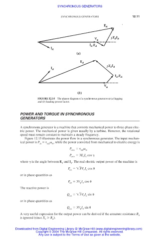
FIGURE 12.14 The phasor diagram of a synchronous generator at (a) lagging
and (b) leading power factor.
POWER AND TORQUE IN SYNCHRONOUS
GENERATORS
A synchronous generator is a machine that converts mechanical power to three-phase elec-
tric power. The mechanical power is given usually by a turbine. However, the rotational
speed must remain constant to maintain a steady frequency.
Figure 12.15 illustrates the power flow in a synchronous generator. The input mechan-
ical power is P , while the power converted from mechanical to electric energy is
in app m
P
conv ind m
P 3E I cos
conv A A
where is the angle between E and I . The real electric output power of the machine is
A A
P 3 V I cos
T L
out
or in phase quantities as
P 3V I cos
out A
The reactive power is
Q 3V I sin
out T L
or in phase quantities as
Q 3V I sin
out A
A very useful expression for the output power can be derived if the armature resistance R
A
is ignored (since X R ).
S A
Downloaded from Digital Engineering Library @ McGraw-Hill (www.digitalengineeringlibrary.com)
Copyright © 2004 The McGraw-Hill Companies. All rights reserved.
Any use is subject to the Terms of Use as given at the website.