
Page 247 - Electrical Equipment Handbook _ Troubleshooting and Maintenance
P. 247
SYNCHRONOUS GENERATORS
12.10 CHAPTER TWELVE
When they are -connected, then
V V
T
Since the three phases are identical except that their phase angles are different, the per-
phase equivalent circuit is used (Fig. 12.12).
THE PHASOR DIAGRAM OF A SYNCHRONOUS
GENERATOR
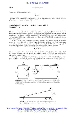
Phasors are used to describe the relationships between ac voltages. Figure 12.13 illustrates
these relationships when the generator is supplying a purely resistive load (at unity power
factor). The total voltage E differs from the terminal voltage V by the resistive and inductive
A
voltage drops. All voltages and currents are referenced to V , which is assumed arbitrarily
to be at angle 0°.
Figure 12.14 illustrates the phasor diagrams of generators operating at lagging and leading
power factors. Notice that for a given phase voltage and armature current, lagging loads
require larger internal generated voltage E than leading loads. Therefore, a larger field
A
current is required for lagging loads to get the same terminal voltage, because
E K
A
where must remain constant to maintain constant frequency. Thus, for a given field
current and magnitude of load current, the terminal voltage for lagging loads is lower than
the one for leading loads.
In real synchronous generators, the winding resistance is much smaller than the synchro-
nous reactance. Therefore, R is often neglected in qualitative studies of voltage variations.
A
FIGURE 12.12 The per-phase equivalent circuit of a synchronous generator. The inter-
nal field circuit resistance and the external variable resistance have been combined into a
single resistor R .
F
FIGURE 12.13 The phasor diagram of a synchronous generator at
unity power factor.
Downloaded from Digital Engineering Library @ McGraw-Hill (www.digitalengineeringlibrary.com)
Copyright © 2004 The McGraw-Hill Companies. All rights reserved.
Any use is subject to the Terms of Use as given at the website.