
Page 249 - Electrical Equipment Handbook _ Troubleshooting and Maintenance
P. 249
SYNCHRONOUS GENERATORS
12.12 CHAPTER TWELVE
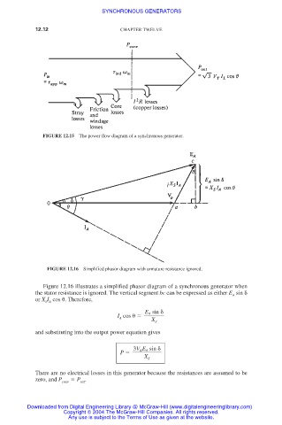
FIGURE 12.15 The power flow diagram of a synchronous generator.
FIGURE 12.16 Simplified phasor diagram with armature resistance ignored.
Figure 12.16 illustrates a simplified phasor diagram of a synchronous generator when
the stator resistance is ignored. The vertical segment bc can be expressed as either E sin
A
or X I cos
. Therefore,
S A
E A sin
I cos
A X
S
and substituting into the output power equation gives
3V E A sin
P
X
S
There are no electrical losses in this generator because the resistances are assumed to be
zero, and P P .
conv out
Downloaded from Digital Engineering Library @ McGraw-Hill (www.digitalengineeringlibrary.com)
Copyright © 2004 The McGraw-Hill Companies. All rights reserved.
Any use is subject to the Terms of Use as given at the website.