
Page 254 - Electrical Equipment Handbook _ Troubleshooting and Maintenance
P. 254
SYNCHRONOUS GENERATORS
SYNCHRONOUS GENERATORS 12.17
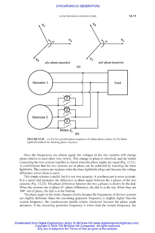
FIGURE 12.20 (a) The two possible phase sequences of a three-phase system. (b) The three-
lightbulb method for checking phase sequence.
Once the frequencies are almost equal, the voltages in the two systems will change
phase relative to each other very slowly. This change in phase is observed, and the switch
connecting the two systems together is closed when the phase angles are equal (Fig. 12.21).
A confirmation that the two systems are in phase can be achieved by watching the three
lightbulbs. The systems are in phase when the three lightbulbs all go out (because the voltage
difference across them is zero).
This simple scheme is useful, but it is not very accurate. A synchroscope is more accurate.
It is a meter that measures the difference in phase angle between the a phases of the two
systems (Fig. 12.22). The phase difference between the two a phases is shown by the dial.
When the systems are in phase (0° phase difference), the dial is at the top. When they are
180° out of phase, the dial is at the bottom.
The phase angle on the meter changes slowly because the frequencies of the two systems
are slightly different. Since the oncoming generator frequency is slightly higher than the
system frequency, the synchroscope needle rotates clockwise because the phase angle
advances. If the oncoming generator frequency is lower than the system frequency, the
Downloaded from Digital Engineering Library @ McGraw-Hill (www.digitalengineeringlibrary.com)
Copyright © 2004 The McGraw-Hill Companies. All rights reserved.
Any use is subject to the Terms of Use as given at the website.