
Page 259 - Electrical Equipment Handbook _ Troubleshooting and Maintenance
P. 259
SYNCHRONOUS GENERATORS
12.22 CHAPTER TWELVE
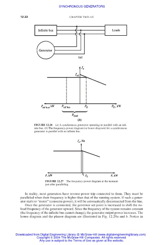
FIGURE 12.26 (a) A synchronous generator operating in parallel with an infi-
nite bus. (b) The frequency-power diagram (or house diagram) for a synchronous
generator in parallel with an infinite bus.
FIGURE 12.27 The frequency-power diagram at the moment
just after paralleling.
In reality, most generators have reverse-power trip connected to them. They must be
paralleled when their frequency is higher than that of the running system. If such a gener-
ator starts to “motor” (consume power), it will be automatically disconnected from the line.
Once the generator is connected, the governor set point is increased to shift the no-
load frequency of the generator upward. Since the frequency of the system remains constant
(the frequency of the infinite bus cannot change), the generator output power increases. The
house diagram and the phasor diagram are illustrated in Fig. 12.29a and b. Notice in
Downloaded from Digital Engineering Library @ McGraw-Hill (www.digitalengineeringlibrary.com)
Copyright © 2004 The McGraw-Hill Companies. All rights reserved.
Any use is subject to the Terms of Use as given at the website.