
Page 261 - Electrical Equipment Handbook _ Troubleshooting and Maintenance
P. 261
SYNCHRONOUS GENERATORS
12.24 CHAPTER TWELVE
the phasor diagram that the magnitude of E ( K ) remains constant because I and
A
F
remained unchanged, while E sin (which is proportional to the output power as long as
A
V remains constant) has increased.
T
When the governor set point is increased, the no-load frequency and the output power
of the generator increase. As the power increases, the magnitude of E remains constant
A
while E sin is increased further.
A
If the output power of the generator is increased until it exceeds the power consumed by
the load, the additional power generated flows back into the system (infinite bus). By def-
inition, the infinite bus can consume or supply any amount of power while the frequency
remains constant. Therefore, the additional power is consumed.
Figure 12.29b illustrates the phasor diagram of the generator when the real power has
been adjusted to the desired value. Notice that at this time, the generator has a slightly leading
power factor. It is acting as a capacitor, requiring reactive power. The field current can be
adjusted so the generator can supply reactive power. However, there are some constraints
on the operation of the generator under these circumstances. The first constraint on the gen-
erator is that when I is changing, the power must remain constant. The power given to the
F
generator is P .
in app m
For a given governor setting, the prime mover of the generator has a fixed torque-speed
characteristic. When the governor set point is changed, the curve moves. Since the generator
is tied to the system (infinite bus), its speed cannot change. Therefore, since the governor
set point and the generator’s speed have not changed, the power supplied by the generator
must remain constant. Since the power supplied does not change when the field current is
changing, then I cos
and E sin (the distance proportional to the power in the phasor
A
A
diagram) cannot change.
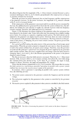
The flux increases when the field current is increased. Therefore, E ( K ) must
A
increase. If E increases while E sin remains constant, then phasor E must slide along
A A A
the constant-power line shown in Fig. 12.30. Since V is constant, the angle of jX I
S A
changes as shown. Therefore, the angle and magnitude of I change.
A
Notice that the distance proportional to Q (I sin
) increases. This means that increasing
A
the field current in a synchronous generator operating in parallel with a power system
(infinite bus) increases the reactive power output of the generator.
In summary, when a generator is operating in parallel with a power system (infinite
bus), the following are true:
1. The power system connected to the generator controls the frequency and the terminal
voltage.
2. The real power supplied by the generator to the system is controlled by the governor
set point.
3. The reactive power supplied by the generator to the system is controlled by the field current.
FIGURE 12.30 The effect of increasing the generator’s field current on the phasor diagram of
the machine.
Downloaded from Digital Engineering Library @ McGraw-Hill (www.digitalengineeringlibrary.com)
Copyright © 2004 The McGraw-Hill Companies. All rights reserved.
Any use is subject to the Terms of Use as given at the website.