
Page 257 - Electrical Equipment Handbook _ Troubleshooting and Maintenance
P. 257
SYNCHRONOUS GENERATORS
12.20 CHAPTER TWELVE
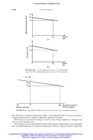
FIGURE 12.23 (a) The speed-power curve for a typical prime
mover. (b) The resulting frequency-power curve for the generator.
FIGURE 12.24 The terminal voltage V -reactive power Q curve for a synchronous generator.
T
This plot has a drooping characteristic that is not generally linear, but most generator
voltage regulators have a feature to make this characteristic linear.
When the no-load terminal voltage set point on the voltage regulator is changed, the
curve can slide up and down.
The frequency-power and terminal voltage-reactive power characteristics play important
roles in parallel operation of synchronous generators. When a single generator is operating
Downloaded from Digital Engineering Library @ McGraw-Hill (www.digitalengineeringlibrary.com)
Copyright © 2004 The McGraw-Hill Companies. All rights reserved.
Any use is subject to the Terms of Use as given at the website.