
Page 258 - Electrical Equipment Handbook _ Troubleshooting and Maintenance
P. 258
SYNCHRONOUS GENERATORS
SYNCHRONOUS GENERATORS 12.21
alone, the real power P and reactive power Q are equal to the amounts demanded by
the loads.
The generator’s controls cannot control the real and reactive power supplied. Therefore,
for a given real power, the generator’s operating frequency f is controlled by the governor
e
set points, and for a given reactive power, the generator’s terminal voltage V is controlled
T
by the field current.
OPERATION OF GENERATORS IN PARALLEL WITH
LARGE POWER SYSTEMS
The power system is usually very large so that nothing the operator of a synchronous gen-
erator connected to it does will have any effect on the power system. An example is the
North American power grid, which is very large so that any action taken by one generator
cannot make an observable change in the overall grid frequency.
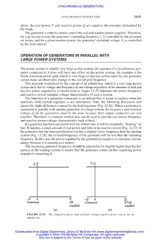
This principle is idealized by the concept of an infinite bus, which is a very large power
system such that its voltage and frequency do not change regardless of the amounts of real and
reactive power supplied to or drawn from it. Figure 12.25 illustrates the power-frequency
and reactive power-terminal voltage characteristics of such a system.
The behavior of a generator connected to an infinite bus is easier to explain when the
automatic field current regulator is not considered. Thus, the following discussion will
ignore the slight differences caused by the field regulator (Fig. 12.26). When a generator is
connected in parallel with another generator or a large system, the frequency and terminal
voltage of all the generators must be the same because their output conductors are tied
together. Therefore, a common vertical axis can be used to plot the real power-frequency
and reactive power-voltage characteristics back to back.
If a generator has been paralleled with the infinite bus, it will be essentially “floating” on
line. It supplies a small amount of real power and little or no reactive power (Fig. 12.27). If
the generator that has been paralleled to line has a slightly lower frequency than the running
system (Fig. 12.28), the no-load frequency of the generator will be less than the operating
frequency. In this case, the power supplied by the generator is negative (it consumes electric
energy because it is running as a motor).
The oncoming generator frequency should be adjusted to be slightly higher than the fre-
quency of the running system to ensure that the generator comes on line supplying power
instead of consuming it.
FIGURE 12.25 The frequency-power and terminal voltage-reactive power curves for an
infinite bus.
Downloaded from Digital Engineering Library @ McGraw-Hill (www.digitalengineeringlibrary.com)
Copyright © 2004 The McGraw-Hill Companies. All rights reserved.
Any use is subject to the Terms of Use as given at the website.