
Page 256 - Electrical Equipment Handbook _ Troubleshooting and Maintenance
P. 256
SYNCHRONOUS GENERATORS
SYNCHRONOUS GENERATORS 12.19
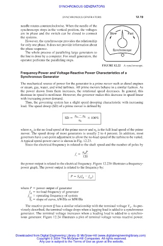
needle rotates counterclockwise. When the needle of the
synchroscope stops in the vertical position, the voltages
are in phase and the switch can be closed to connect
the systems.
However, the synchroscope provides the relationship
for only one phase. It does not provide information about
the phase sequence.
The whole process of paralleling large generators to
the line is done by a computer. For small generators, the
operator performs the paralleling steps.
FIGURE 12.22 A synchroscope.
Frequency-Power and Voltage-Reactive Power Characteristics of a
Synchronous Generator
The mechanical source of power for the generator is a prime mover such as diesel engines
or steam, gas, water, and wind turbines. All prime movers behave in a similar fashion. As
the power drawn from them increases, the rotational speed decreases. In general, this
decrease in speed is nonlinear. However, the governor makes this decrease in speed linear
with increasing power demand.
Thus, the governing system has a slight speed drooping characteristic with increasing
load. The speed droop (SD) of a prime mover is defined by
n nl n fl
SD
100%
n fl
where n is the no-load speed of the prime mover and n is the full-load speed of the prime
nl fl
mover. The speed droop of most generators is usually 2 to 4 percent. In addition, most
governors have a set-point adjustment to allow the no-load speed of the turbine to be varied.
A typical speed-power curve is shown in Fig. 12.23.
Since the electrical frequency is related to the shaft speed and the number of poles by
P
n m
f
e
120
the power output is related to the electrical frequency. Figure 12.23b illustrates a frequency-
power graph. The power output is related to the frequency by:
P S (f f )
P nl sys
where P power output of generator
f no-load frequency of generator
nl
f operating frequency of system
sys
S slope of curve, kW/Hz or MW/Hz
P
The reactive power Q has a similar relationship with the terminal voltage V . As pre-
T
viously described, the terminal voltage drops when a lagging load is added to a synchronous
generator. The terminal voltage increases when a leading load is added to a synchro-
nous generator. Figure 12.24 illustrates a plot of terminal voltage versus reactive power.
Downloaded from Digital Engineering Library @ McGraw-Hill (www.digitalengineeringlibrary.com)
Copyright © 2004 The McGraw-Hill Companies. All rights reserved.
Any use is subject to the Terms of Use as given at the website.