
Page 263 - Electrical Equipment Handbook _ Troubleshooting and Maintenance
P. 263
SYNCHRONOUS GENERATORS
12.26 CHAPTER TWELVE
Therefore, the maximum allowable heating determines the maximum field current for the
machine. Since E K , this also determines the maximum acceptable E . Since there
A A
is a maximum value for I and E , there is a minimum acceptable power factor of the gen-
F A
erator when it is operating at the rated MVA.
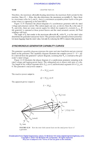
Figure 12.31 illustrates the phasor diagram of a synchronous generator with the rated
voltage and armature current. The current angle can vary, as shown. Since E is the sum of
A
V and jX I , there are some current angles for which the required E exceeds E A,max . If
A
S A
the generator is operated at these power factors and the rated armature current, the field
windings will burn.
The angle of I that results in the maximum allowable E while V is at the rated value
A A
determines the generator rated power factor. The generator can be operated at lower power fac-
tor (more lagging) than the rated value, but only by reducing the MVA output of the generator.
SYNCHRONOUS GENERATOR CAPABILITY CURVES
The generator capability diagram expresses the stator and rotor heat limits and any external
limits on the generator. The capability diagram illustrates the complex power S P jQ.
It is derived from the generator’s phasor diagram, assuming that V is constant at the gen-
erator’s rated voltage.
Figure 12.32 illustrates the phasor diagram of a synchronous generator operating at its
rated voltage and lagging power factor. The orthogonal axis is drawn with units of volts.
The length of the vertical segment AB is X I cos
, and horizontal segment OA is X I sin
S A S A
. The generator’s real power output is
P 3V I cos
A
The reactive power output is
Q 3V I sin
A
The apparent power output is
S 3V I
A
FIGURE 12.31 How the rotor field current limit sets the rated power factor of
a generator.
Downloaded from Digital Engineering Library @ McGraw-Hill (www.digitalengineeringlibrary.com)
Copyright © 2004 The McGraw-Hill Companies. All rights reserved.
Any use is subject to the Terms of Use as given at the website.