
Page 264 - Electrical Equipment Handbook _ Troubleshooting and Maintenance
P. 264
SYNCHRONOUS GENERATORS
SYNCHRONOUS GENERATORS 12.27
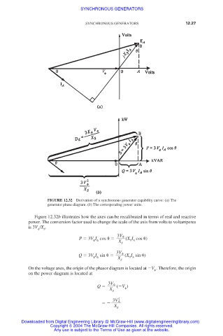
FIGURE 12.32 Derivation of a synchronous generator capability curve: (a) The
generator phase diagram. (b) The corresponding power units.
Figure 12.32b illustrates how the axes can be recalibrated in terms of real and reactive
power. The conversion factor used to change the scale of the axis from volts to voltamperes
is 3V /X .
S
3V
P 3V I cos
(X I cos
)
S A
X
S
3V
Q 3V I sin
(X I sin
)
X S A
S
On the voltage axes, the origin of the phasor diagram is located at V . Therefore, the origin
on the power diagram is located at
3V
Q ( V )
X
S
2
3V
X
S
Downloaded from Digital Engineering Library @ McGraw-Hill (www.digitalengineeringlibrary.com)
Copyright © 2004 The McGraw-Hill Companies. All rights reserved.
Any use is subject to the Terms of Use as given at the website.