
Page 36 - Electrical Equipment Handbook _ Troubleshooting and Maintenance
P. 36
INTRODUCTION TO MACHINERY PRINCIPLES
INTRODUCTION TO MACHINERY PRINCIPLES 2.9
Based on Faraday’s law, a flux changing with time induces a voltage within a ferro-
magnetic core in a similar manner as it would in a wire wrapped around the core. These
voltages can generate swirls of current inside the core. They are similar to the eddies seen
at the edges of a river. They are called eddy currents. Energy is dissipated by these flow-
ing eddy currents. The lost energy heats the iron core. Eddy current losses are proportional
to the length of the paths they follow within the core. For this reason, all ferromagnetic
cores subjected to alternating fluxes are made of many small strips, or laminations. The
strips are insulated on both sides to reduce the paths of the eddy currents. The strips are
oriented in a parallel direction to the magnetic flux. The eddy current losses have the fol-
lowing characteristics:
● They are proportional to the square of the lamination thickness.
● They are inversely proportional to the electrical resistivity of the material.
The thickness of the laminations is between 0.5 and 5 mm in power equipment and
between 0.01 and 0.5 mm in electronic equipment. The volume of a material increases
when it is laminated. The stacking factor is the ratio of the actual volume of the magnetic
material to its total volume after it has been laminated. This is an important variable for
accurately calculating the flux densities in magnetic materials. Table 2.2 lists the typical
stacking factors for different lamination thicknesses. Since hysteresis losses and eddy cur-
rent losses occur in the core, their sum is called core losses.
CORE LOSS VALUES
Figure 2.6 shows the core loss data for M-15, which is a 3 percent silicon steel. This mag-
netic material is used in many transformers and small motors. Figure 2.7a and b shows the
core loss data for a nickel alloy widely used in electronics equipment (48 NI) and a ferrite
material, respectively.
PERMANENT MAGNETS
Permanent magnets are a common excitation source for rotating machines. The perfor-
mance of a permanent magnet depends on how the magnet is installed in the machine and
whether it was magnetized before or after installation. Most permanent magnets, except for
the new neodymium-iron-boron magnet, are not machinable. They must be used in the
machine as obtained from the manufacturer. Table 2.3 lists the main characteristics of com-
mon permanent magnets.
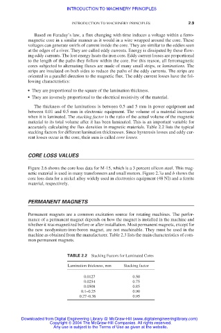
TABLE 2.2 Stacking Factors for Laminated Cores
Lamination thickness, mm Stacking factor
0.0127 0.50
0.0254 0.75
0.0508 0.85
0.1–0.25 0.90
0.27–0.36 0.95
Downloaded from Digital Engineering Library @ McGraw-Hill (www.digitalengineeringlibrary.com)
Copyright © 2004 The McGraw-Hill Companies. All rights reserved.
Any use is subject to the Terms of Use as given at the website.