
Page 37 - Electrical Equipment Handbook _ Troubleshooting and Maintenance
P. 37
INTRODUCTION TO MACHINERY PRINCIPLES
2.10 CHAPTER TWO
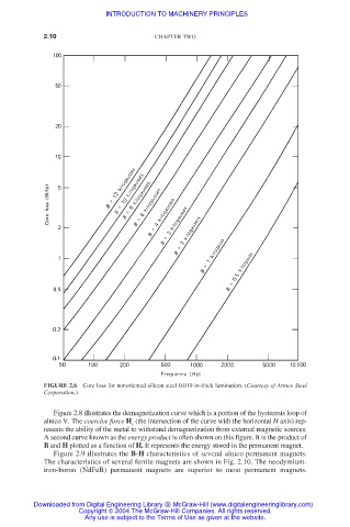
FIGURE 2.6 Core loss for nonoriented silicon steel 0.019-in-thick lamination. (Courtesy of Armco Steel
Corporation.)
Figure 2.8 illustrates the demagnetization curve which is a portion of the hysteresis loop of
alnico V. The coercive force H (the intersection of the curve with the horizontal H axis) rep-
c
resents the ability of the metal to withstand demagnetization from external magnetic sources.
A second curve known as the energy product is often shown on this figure. It is the product of
B and H plotted as a function of H. It represents the energy stored in the permanent magnet.
Figure 2.9 illustrates the B-H characteristics of several alnico permanent magnets.
The characteristics of several ferrite magnets are shown in Fig. 2.10. The neodymium-
iron-boron (NdFeB) permanent magnets are superior to most permanent magnets.
Downloaded from Digital Engineering Library @ McGraw-Hill (www.digitalengineeringlibrary.com)
Copyright © 2004 The McGraw-Hill Companies. All rights reserved.
Any use is subject to the Terms of Use as given at the website.