
Page 82 - Electrical Installation in Hazardous Area
P. 82
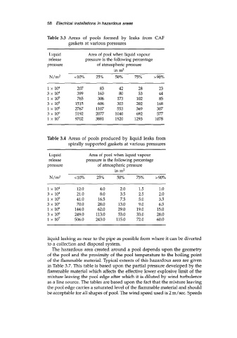
58  Electrical installations in hazardous areas

                     Table 3.3  Areas  of  pools  formed  by  leaks  from  CAF
                              gaskets at various pressures

                      Liquid           Area  of  pool when liquid vapour
                      release         pressure is the following percentage
                     pressure              of  atmospheric pressure
                                                  in m2
                      N/mZ       <lo%     25%      50%     75%     >go%

                     1 x  104     207       83      42       28      23
                     3 x 10⁴      399      160      80       53      44
                     1 x  105     765      306      173     102       85
                     3 x  105     1515     606      303     202      168
                     1 x 10⁶     2767     1107     553      369      307
                     3 x  106    5192     2077     1040     692      577
                     1 x 10⁷     9702     3881     1920    1293     1078


                     Table 3.4  Areas of  pools produced by liquid leaks from
                              spirally supported gaskets at various pressures

                      Liquid           Area of  pool when liquid vapour
                      release         pressure is the following percentage
                     pressure              of  atmospheric pressure
                                                  in m2
                      N/m2       <lo%      25%     50%      75%     >go%

                     1 x  104     12.0      4.0      2.0     1.5      1.0
                     3x10⁴        21.0      8.0      3.5     2.5     2.0
                     1 x 10⁵      41 .O    16.5      7.5     5.0     3.5
                     3 x 10⁵      70.0     28.0     13.0     9.0     6.5
                     1 x  106    144.0     62.0     29.0    19.0     15.0
                     3 x 10⁶     249.0    113.0     53.0    33.0     28.0
                     1 x 10⁷     506.0    243.0    115.0    72.0     60.0


                     liquid leaking as near to the pipe as possible from where it can be diverted
                     to a collection and disposal system.
                       The hazardous area created around a pool depends upon the geometry
                     of  the pool and the proximity of  the pool temperature to the boiling point
                     of  the flammable material. Typical extents of  this hazardous area are given
                     in Table 3.7. This table is based upon the partial pressure developed by the
                     flammable material which affects the effective lower explosive limit of  the
                     mixture leaving the pool edge after which it is diluted by wind turbulence
                     as a line source. The tables are based upon the fact that the mixture leaving
                     the pool edge carries a saturated level of the flammable material and should
                     be acceptable for all shapes of pool. The wind speed used is 2 m/sec. Speeds