
Page 113 - Electrical Safety of Low Voltage Systems
P. 113
96 Chapter Six
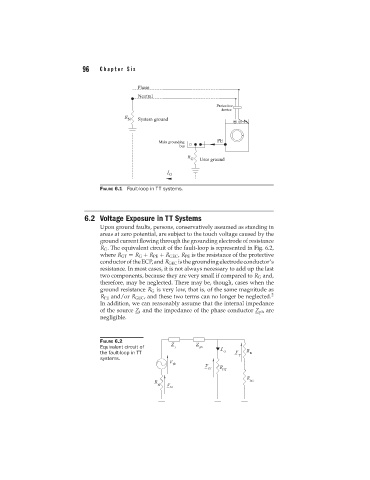
FIGURE 6.1 Fault-loop in TT systems.
6.2 Voltage Exposure in TT Systems
Upon ground faults, persons, conservatively assumed as standing in
areas at zero potential, are subject to the touch voltage caused by the
ground current flowing through the grounding electrode of resistance
R G . The equivalent circuit of the fault-loop is represented in Fig. 6.2,
where R GT = R G + R PE + R GEC , R PE is the resistance of the protective
conductoroftheECP,and R GEC isthegroundingelectrodeconductor’s
resistance. In most cases, it is not always necessary to add up the last
two components, because they are very small if compared to R G and,
therefore, may be neglected. There may be, though, cases when the
ground resistance R G is very low, that is, of the same magnitude as
R PE and/or R GEC , and these two terms can no longer be neglected. 2
In addition, we can reasonably assume that the internal impedance
of the source Z i and the impedance of the phase conductor Z ph are
negligible.
FIGURE 6.2
Equivalent circuit of
the fault-loop in TT
systems.