
Page 117 - Electrical Safety of Low Voltage Systems
P. 117
100 Chapter Six
Maximum Disconnection
Voltage Range (V) Times t a (s)
50 < V ph ≤ 120 0.3
120 < V ph ≤ 230 0.2
230 < V ph ≤ 400 0.07
V ph > 400 0.04
TABLE 6.1 Maximum Disconnection Times as a Function
of the Nominal Voltage of the System
t a . If Eq. (6.4) is fulfilled, the overcurrent device will trip within a time
that will prevent harmful effects to persons touching live parts.
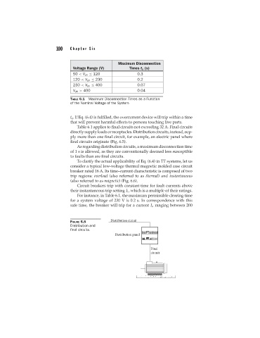
Table 6.1 applies to final circuits not exceeding 32 A. Final circuits
directlysupplyloadsorreceptacles.Distributioncircuits,instead,sup-
ply more than one final circuit, for example, an electric panel where
final circuits originate (Fig. 6.5).
As regarding distribution circuits, a maximum disconnection time
of1sis allowed, as they are conventionally deemed less susceptible
to faults than are final circuits.
To clarify the actual applicability of Eq. (6.4) in TT systems, let us
consider a typical low-voltage thermal magnetic molded case circuit
breaker rated 16 A. Its time–current characteristic is composed of two
trip regions: overload (also referred to as thermal) and instantaneous
(also referred to as magnetic) (Fig. 6.6).
Circuit breakers trip with constant time for fault currents above
their instantaneous trip setting I i , which is a multiple of their ratings.
For instance, in Table 6.1, the maximum permissible clearing time
for a system voltage of 230 V is 0.2 s. In correspondence with this
safe time, the breaker will trip for a current I a ranging between 200
FIGURE 6.5
Distribution and
final circuits.