
Page 116 - Electrical Safety of Low Voltage Systems
P. 116
TT Grounding System 99
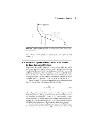
FIGURE 6.4 Time–voltage safety curve and inverse time–current curve of the
protective device.
time t P . Safety is achieved if t G < t P for any given value of ground-fault
current I G .
6.3 Protection Against Indirect Contact in TT Systems
by Using Overcurrent Devices
Overcurrent devices [i.e., electrical circuit breakers (CBs) and fuses]
are present in any installation to protect cables and equipment against
overloads and short circuits. Standard values for CBs for household
4
and similar applications are (in amperes): 6, 10, 13, 16, 20, 25, 32, 40,
5
50, 63, 80, 100, 125. The North American National Electrical Code lists,
among other sizes, for the fixed-trip inverse time CB the following (in
amperes): 15, 20, 25, 30, 35, 40, 45, 50, 60, 70, 80, 90, 100, 110, 125.
Circuit breakers (or fuses) can be employed as a protection against
indirect contact if the following condition is satisfied:
V ph
I G = ≥ I a (6.4)
Z Loop
where Z Loop is the series of the impedances of the components that
form the ground-fault loop, and specifically the source, the line con-
ductor up to the fault point, R GT and R N . V ph is the nominal voltage
to ground and I a is the operating current causing the automatic oper-
ation of the overcurrent protective device within the time specified in
IEC Table 6.1 as a function of the nominal voltage of the system.
Equation (6.4) requires that the ground current be so high as to al-
low a prompt disconnection of the supply within a time not exceeding