
Page 130 - Electrical Safety of Low Voltage Systems
P. 130
TT Grounding System 113
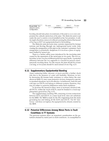
FIGURE 6.21 Two
dielectric joints
configuration.
bonding should take place downstream of the joint so as to not com-
promise the cathodic protection of the pipe. The dielectric joint is not
under the user’s control, even if installed on his/her premises. A util-
ity might, therefore, remove it without warning the client of the hazard
of having an ECP not equipotentialized in the building.
The dielectric joint prevents stray currents, impressed by foreign
systems and flowing through any underground metal work, from
causing the energization of the pipe in the customer’s premises. Such
energization is potentially dangerous if it involves a piece of equip-
ment fuelled by natural gas.
There is a further safety issue introduced by the insulating joint
caused by the separation of the metal pipe in two parts. The two ex-
tremities, in fact, may be at different potentials upon faults. A potential
difference between the two segments is a hazard for persons simul-
taneously touching them. For this reason, the joint should be at least
2 m long, or two joints should be used instead of one (Fig. 6.21).
6.11 Supplementary Equipotential Bonding
Areas containing baths, showers, or pools provide a further shock
risk due to the presence of water and humidity. Moisture, in fact,
by decreasing the human body resistance to values below the ones
shown in Table 5.2, may cause protective devices, designed to operate
in standard situations, not to be effective. In bathrooms, both hot and
cold taps are EXCPs and belong to different systems; therefore, they
may be subject to potential differences under fault conditions.
To decrease the hazard in these areas at increased electrical risk,
all EXCPs, within the reach of ECPs, must be bonded to a local sup-
plementary ground bus (Fig. 6.22).
The supplementary bonding (SB), consisting of extra connections
between ECPs and EXCPs at a more local level, does not substitute
for the MEB. The MEB is made by the PEs originating from the main
grounding bus and linking all the ECPs and EXCPs. The SB “rein-
forces,” and does not replace, the equipotentiality already created by
the MEB.
6.12 Potential Differences Among Metal Parts in Fault
Conditions in TT Systems
The previous sections allow an important consideration on the po-
tentials attained by metal parts in fault conditions. As exemplified in