
Page 135 - Electrical Safety of Low Voltage Systems
P. 135
118 Chapter Seven
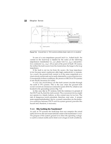
FIGURE 7.1 Ground fault in TN-S systems (three-phase load with no neutral).
In case of a zero-impedance ground fault (i.e., bolted fault), the
current in the fault-loop is limited by the series of the following
impedances: transformer (i.e., Z i ), phase wire (i.e., Z ph ), and protec-
tive conductor (i.e., Z PE ). All as seen at the point of fault. Of course,
the farther the fault occurs from the transformer, the larger is the loop
impedance.
If the fault is not too far from the source, the loop impedance
is low because metal conductors offer high conductivity to currents.
As a result, the ground-fault current is of the same magnitude as a
short-circuit current and can be easily detectedby overcurrent devices.
Consequently,intheseconditions,thepresenceofRCDsinTNsystems
is not strictly necessary for safety.
In only one circumstance can the fault current circulate through
the earth in TN systems. This is the case when the ground fault
occurs toward an extraneous-conductive-parts (EXCPs), which is not
bonded to the grounding system (Fig. 7.2).
In this case, like in TT systems, both the resistance to ground of
the EXCP and R N limit the fault current. The overcurrent device might
not operate in a timely fashion, as this current may be too low. The
risk of dangerous touch potentials, therefore, may arise. A proper
main equipotentialization, that is, a sound connection via the protec-
tive conductor between EXCPs and the system ground, prevents this
hazard and, therefore, is necessary.
7.1.1 Why Earthing the Transformer?
As said, in TN systems the fault-loop does not comprise the actual
earth; however, the user must earth the center of its transformer’s wye.
The purpose of the system ground is to allow the operating voltage-
to-earth to remain stable and to limit overvoltages in fault conditions.