
Page 138 - Electrical Safety of Low Voltage Systems
P. 138
TN Grounding System 121
It should be noted that Z Th (magnitude of fractions of ohms) could
be neglected, as it is much smaller than the series (R B + R BG ). As a
consequence, there is almost no voltage drop on Z Th and the fault-loop
is virtually an ideal voltage source. The person’s total resistance does
not significantly change the voltage output V Th in case of a contact
and, therefore, V Th equals V ST .
As phase and protective conductor belonging to a same circuit
usually run together, they are characterized by the same length and
type of installation. Therefore, the ratio of their impedances is constant
along their entire route up to the fault location. Ergo, Eq. (7.1) shows
that the magnitude of V ST remains constant regardless of the location
of the fault as long as the ratio of Z ph to Z PE is constant.
If the protective conductor has the same cross section as the phase,
Eq. (7.1) yields: V ST = V ph /2. If the PE has half section of the phase
2
conductor (i.e., Z PE = 2Z ph ), we obtain a larger prospective touch
voltage: V ST = 2V ph /3. Thus, the touch voltage increases where the
PE has a lower section than the phase conductor.
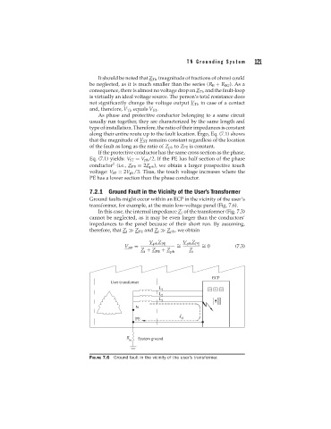
7.2.1 Ground Fault in the Vicinity of the User’s Transformer
Ground faults might occur within an ECP in the vicinity of the user’s
transformer, for example, at the main low-voltage panel (Fig. 7.6).
In this case, the internal impedance Z i of the transformer (Fig. 7.3)
cannot be neglected, as it may be even larger than the conductors’
impedances to the panel because of their short run. By assuming,
therefore, that Z i Z PE and Z i Z ph , we obtain
V ph Z PE V ph Z PE
V = ∼ = 0 (7.3)
∼
ST =
Z + Z + Z Z
i PE ph i
FIGURE 7.6 Ground fault in the vicinity of the user’s transformer.