
Page 139 - Electrical Safety of Low Voltage Systems
P. 139
122 Chapter Seven
In the above conditions of proximity to the transformer, the indirect
contact is hardly ever dangerous.
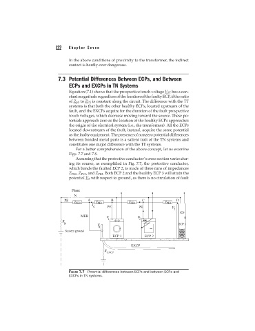
7.3 Potential Differences Between ECPs, and Between
ECPs and EXCPs in TN Systems
Equation (7.1) shows that the prospective touch voltage V ST has a con-
stant magnitude regardless of the location of the faulty ECP, if the ratio
of Z ph to Z PE is constant along the circuit. The difference with the TT
systems is that both the other healthy ECPs, located upstream of the
fault, and the EXCPs acquire for the duration of the fault prospective
touch voltages, which decrease moving toward the source. These po-
tentials approach zero as the location of the healthy ECPs approaches
the origin of the electrical system (i.e., the transformer). All the ECPs
located downstream of the fault, instead, acquire the same potential
as the faulty equipment. The presence of nonzero potential differences
between bonded metal parts is a salient trait of the TN systems and
constitutes one major difference with the TT systems.
For a better comprehension of the above concept, let us examine
Figs. 7.7 and 7.8.
Assuming that the protective conductor’s cross section varies dur-
ing its course, as exemplified in Fig. 7.7, the protective conductor,
which bonds the faulted ECP 2, is made of three runs of impedances
Z PE0 , Z PE1 , and Z PE2 . Both ECP 2 and the healthy ECP 3 will attain the
potential V 2 with respect to ground, as there is no circulation of fault
FIGURE 7.7 Potential differences between ECPs and between ECPs and
EXCPs in TN systems.