
Page 137 - Electrical Safety of Low Voltage Systems
P. 137
120 Chapter Seven
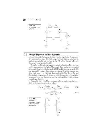
FIGURE 7.4
Fault-loop in TN-S
systems.
7.2 Voltage Exposure in TN-S Systems
Let us conservatively assume that persons are exposed to the prospec-
1
tive touch voltage V ST . The fault-loop, not involving the actual earth,
is diagrammatically represented in Fig. 7.4, where the symbols have
the same meaning as in Fig. 6.2.
In order to obtain the prospective touch voltage to which persons
will be exposed, we apply the Thevenin’s theorem between point A
(i.e., point of contact with the faulted ECP) and G (i.e., the ground). We
can reasonably neglect the internal impedance Z i of the transformer
if the fault occurs at a sufficient distance from it. Modules of Z ph and
Z PE , in fact, proportionally increase with the quantity of conductor
interposed between the source and the fault, and they both become
much larger than Z i .
Figure 7.5 shows the Thevenin’s equivalent circuit as seen between
the two aforementioned points, where
V ph Z PE V ph
V = = = V (7.1)
∼
Th ST
Z + Z (Z /Z ) + 1
ph PE ph PE
Z ph Z PE
Z = (7.2)
Th + R N
Z + Z
ph PE
FIGURE 7.5
Thevenin’s
equivalent circuit
between point A
and point G.