
Page 140 - Electrical Safety of Low Voltage Systems
P. 140
TN Grounding System 123
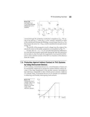
FIGURE 7.8
Equivalent fault
circuit and potential
differences in TN
systems.
current through the protective conductor’s impedance Z PE3 . The se-
ries of R N and R EXCP , where R EXCP is the “natural” resistance to earth
of the metalwork entering the building, is much larger than Z PE0 . For
this reason, the series R N + R EXCP can be considered as an open circuit
in Fig. 7.8.
The profile of the prospective touch voltage from the origin of the
electrical system to the faulty equipment is exemplified in Fig. 7.9.
In sum, since V 0 < V 1 < V 2 , we can infer that potential differences
do exist between bonded metal parts during the time the protective
device takes to clear the fault; the magnitude of such potential differ-
ences varies with the location of the ECP as a function of the distance
from the supply.
7.4 Protection Against Indirect Contact in TN-S Systems
by Using Overcurrent Devices
In TN systems, overcurrent devices (i.e., circuit breakers or fuses) can
be successfully employed for protection against indirect contact, be-
cause of the large magnitude of the ground currents circulating in
the fault-loop, comparable to that of short-circuit currents. Unlike in
TT systems, then, overcurrent devices in TN systems are facilitated
in detecting, and thereby interrupting, fault currents.
FIGURE 7.9
Prospective touch
voltage profile as a
function of the
distance from the
origin of the
electrical system.