
Page 143 - Electrical Safety of Low Voltage Systems
P. 143
126 Chapter Seven
In the above nonstandard circumstances, to ensure protection
against indirect contact, RCDs may be employed together with a fully
rated protective conductor.
7.4.1 Calculation of the Approximate Minimum Value of the
Phase-to-Protective Conductor Fault Current
As said, ground faults cause short circuits due to the highly conductive
nature of the fault-loop in TN systems. The minimum ground-fault
current can be approximately calculated at the farthest fault point,
under the following assumptions:
1. The supply voltage reduces to 80% of its nominal value
due to the voltage drop caused by the ground-fault current.
This assumption is deemed acceptable only if the combined
impedance of the fault-loop conductors is much greater than
the source’s impedance.
2. The resistance of conductors included in the fault-loop in-
◦
creases by 50% with respect to their 20 C value because of the
heat from the ground-fault current.
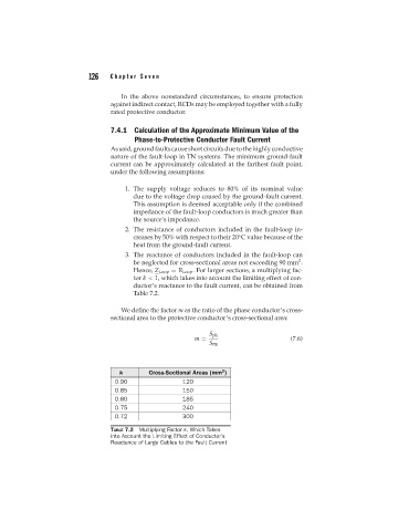
3. The reactance of conductors included in the fault-loop can
2
be neglected for cross-sectional areas not exceeding 90 mm .
Hence, Z Loop = R Loop . For larger sections, a multiplying fac-
tor k < 1, which takes into account the limiting effect of con-
ductor’s reactance to the fault current, can be obtained from
Table 7.2.
We define the factor m as the ratio of the phase conductor’s cross-
sectional area to the protective conductor’s cross-sectional area:
S ph
m = (7.6)
S PE
2
k Cross-Sectional Areas (mm )
0.90 120
0.85 150
0.80 185
0.75 240
0.72 300
TABLE 7.2 Multiplying Factor k, Which Takes
into Account the Limiting Effect of Conductor’s
Reactance of Large Cables to the Fault Current