
Page 146 - Electrical Safety of Low Voltage Systems
P. 146
TN Grounding System 129
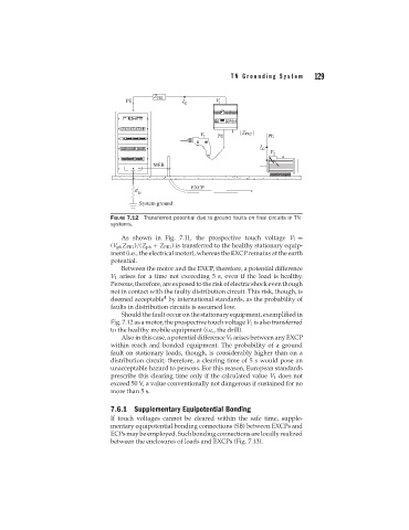
FIGURE 7.12 Transferred potential due to ground faults on final circuits in TN
systems.
As shown in Fig. 7.11, the prospective touch voltage V 1 =
(V ph Z PE1 )/(Z ph + Z PE1 ) is transferred to the healthy stationary equip-
ment (i.e., the electrical motor), whereas the EXCP remains at the earth
potential.
Between the motor and the EXCP, therefore, a potential difference
V 1 arises for a time not exceeding 5 s, even if the load is healthy.
Persons,therefore,areexposedtotheriskofelectricshockeventhough
not in contact with the faulty distribution circuit. This risk, though, is
4
deemed acceptable by international standards, as the probability of
faults in distribution circuits is assumed low.
Should the fault occur on the stationary equipment, exemplified in
Fig. 7.12 as a motor, the prospective touch voltage V 1 is also transferred
to the healthy mobile equipment (i.e., the drill).
Also in this case, a potential difference V 1 arises between any EXCP
within reach and bonded equipment. The probability of a ground
fault on stationary loads, though, is considerably higher than on a
distribution circuit; therefore, a clearing time of 5 s would pose an
unacceptable hazard to persons. For this reason, European standards
prescribe this clearing time only if the calculated value V 1 does not
exceed 50 V, a value conventionally not dangerous if sustained for no
more than 5 s.
7.6.1 Supplementary Equipotential Bonding
If touch voltages cannot be cleared within the safe time, supple-
mentary equipotential bonding connections (SB) between EXCPs and
ECPs may be employed. Such bonding connections are locally realized
between the enclosures of loads and EXCPs (Fig. 7.13).