
Page 149 - Electrical Safety of Low Voltage Systems
P. 149
132 Chapter Seven
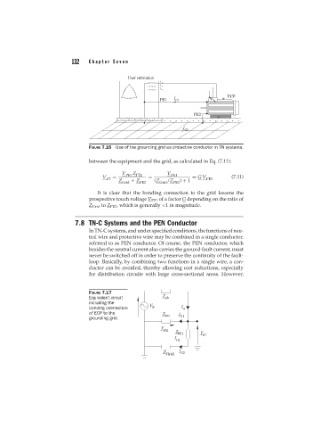
FIGURE 7.16 Use of the grounding grid as protective conductor in TN systems.
between the equipment and the grid, as calculated in Eq. (7.11):
V PE1 Z PE2 V PE1
V = = = G V (7.11)
ST PE1
Z Grid + Z PE2 (Z Grid /Z PE2 ) + 1
It is clear that the bonding connection to the grid lessens the
prospective touch voltage V PE1 of a factor G depending on the ratio of
Z Grid to Z PE2 , which is generally <1 in magnitude.
7.8 TN-C Systems and the PEN Conductor
In TN-C systems, and under specified conditions, the functions of neu-
tral wire and protective wire may be combined in a single conductor,
referred to as PEN conductor. Of course, the PEN conductor, which
besides the neutral current also carries the ground-fault current, must
never be switched off in order to preserve the continuity of the fault-
loop. Basically, by combining two functions in a single wire, a con-
ductor can be avoided, thereby allowing cost reductions, especially
for distribution circuits with large cross-sectional areas. However,
FIGURE 7.17
Equivalent circuit
including the
bonding connection
of ECP to the
grounding grid.