
Page 148 - Electrical Safety of Low Voltage Systems
P. 148
TN Grounding System 131
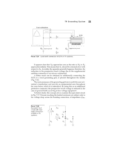
FIGURE 7.14 Local earth connection of ECPs in TN systems.
It appears clear that V ST approaches zero as the ratio of R N to R G
approaches infinity. This means that R G should be extremely low with
respect to R N . In reality, the opposite generally happens; therefore, the
reduction in the prospective touch voltage due to the supplemental
earthing connection is not always substantial.
A better result can be obtained by additionally connecting the
ECPs to a local grounding grid, if present throughout the facility
(Fig. 7.16).
The main purposes of the grounding grid are to earth the user sub-
station’s transformer and provide an equipotential area throughout
the zone below which it is embedded. By using this as an additional
protective conductor, the prospective touch voltage is reduced in the
case of ground faults occurring at low-voltage equipment.
To better clarify this concept, let us examine the equivalent circuit
in Fig. 7.17. Persons touching the faulted enclosure are subject only to
the voltage drop across the bonding connection, of impedance Z PE2 ,
FIGURE 7.15
Equivalent fault
circuit with local
earth connection
of ECPs in TN
systems.