
Page 147 - Electrical Safety of Low Voltage Systems
P. 147
130 Chapter Seven
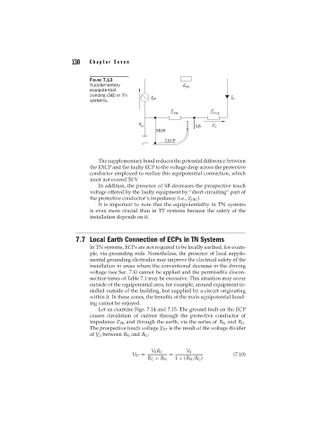
FIGURE 7.13
Supplementary
equipotential
bonding (SB) in TN
systems.
The supplementary bond reduces the potential difference between
the EXCP and the faulty ECP to the voltage drop across the protective
conductor employed to realize this equipotential connection, which
must not exceed 50 V.
In addition, the presence of SB decreases the prospective touch
voltage offered by the faulty equipment by “short circuiting” part of
the protective conductor’s impedance (i.e., Z PE1 ).
It is important to note that the equipotentiality in TN systems
is even more crucial than in TT systems because the safety of the
installation depends on it.
7.7 Local Earth Connection of ECPs in TN Systems
In TN systems, ECPs are not required to be locally earthed, for exam-
ple, via grounding rods. Nonetheless, the presence of local supple-
mental grounding electrodes may improve the electrical safety of the
installation in areas where the conventional decrease in the driving
voltage (see Sec. 7.4) cannot be applied and the permissible discon-
nection times of Table 7.1 may be excessive. This situation may occur
outside of the equipotential area, for example, around equipment in-
stalled outside of the building, but supplied by a circuit originating
within it. In these zones, the benefits of the main equipotential bond-
ing cannot be enjoyed.
Let us examine Figs. 7.14 and 7.15. The ground fault on the ECP
causes circulation of current through the protective conductor of
impedance Z PE and through the earth, via the series of R N and R G .
The prospective touch voltage V ST is the result of the voltage divider
of V 0 between R N and R G :
V 0 R G V 0
V ST = = (7.10)
R G + R N 1 + (R N /R G )