
Page 153 - Electrical Safety of Low Voltage Systems
P. 153
136 Chapter Seven
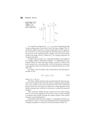
FIGURE 7.22 Touch
voltage in TN
systems due to
high-voltage faults.
As a result, the component I S = I F −I G , by not circulating through
the grounding system, lowers both touch and step voltages. This cir-
cumstance might permit less stringent parameters for the design of
the electrode (e.g., the ground grid), by allowing larger earth resis-
tances for it. In the normal practice, though, one can conservatively
consider the larger value I F , instead of I G , as a design parameter for
sizing the electrode.
In high-voltage systems (e.g., industrial facilities), and unlike in
7
low-voltage systems, European standards, in establishing the per-
missible limits for touch and step voltages, assume in series to the
body resistance R B , conventionally 1 k , and the person resistance-
to-ground R BG (Fig. 4.15), the resistance of standard footwear of 1 k 8
(Fig. 7.22).
For faults on the secondary side of substations, the following in-
equality is true:
V ≤ V ≤ V (7.12)
T ST G
where V G = R G I .
F
The touch voltage persists in the system during the time the pro-
tective device takes to clear the fault. However, primary ground faults
may occur outside of the zone of protection of the user’s protective
device. In this case, the duration of the touch voltage depends on the
utility’s clearing time, which is out of the user’s control and cannot be
changed.
Thus, electrical utilities should communicate the fault clearing
time as well as the magnitude of the earth current so that strategies
to minimize the hazards through the proper design of the ground
electrode can be implemented.
Permissible limits of touch voltages V TP compatible with the stan-
dard person in Fig. 7.22 have been elaborated in the aforementioned
European standard as a function of the fault duration (Table 7.3).