
Page 156 - Electrical Safety of Low Voltage Systems
P. 156
TN Grounding System 139
If the touch voltage exceeds the permissible values given in Table
7.3, corrective mitigation measures must be taken. One might be to
spread a layer of asphalt on the soil around the substation so as to
increase the person’s resistance to earth.
7.11 Step Voltage
Asdiscussedintheprevioussections,attheoccurrenceofhigh-voltage
ground faults, high currents may flow through the actual earth. In
addition to touch voltages, this circulation of current exposes persons
to step voltages, that is, potential differences between two distinct
points of the earth, conventionally taken 1 m apart.
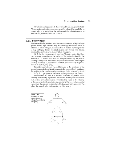
We define the prospective step voltage V SS as the potential differ-
ence between two points on the surface of the earth, displaced by the
distance of 1 m, when the earth is not being stepped on by the person.
The step voltage V S is defined as the potential difference, which a per-
son may be subject to, between the two feet, conventionally displaced
by 1 m. It is always V S ≤ V SS .
The difference between V SS and V S is due to the resistance of the
persontoground R BG ,whichisinseriestotheperson’sbodyresistance
R B , and limits the circulation of current through the person (Fig. 7.24).
In Fig. 7.25, prospective and the actual step voltages are shown.
As examined in Chap. 4, in outdoor locations, R BG can be calcu-
lated by considering a person’s feet as two round plate electrodes,
each with a ground resistance approximately equal to 4 , where
is the superficial soil resistivity. By assuming the two feet as parallel
electrodes, R BG equals 2 ; therefore, V S decreases with respect to V SS ,
when the superficial resistivity of the soil increases.
FIGURE 7.24
Diffrence between
prospective step
voltage V SS and step
voltage V S .