
Page 175 - Electrical Safety of Low Voltage Systems
P. 175
158 Chapter Nine
V ST1 on ECP 1. We obtain
√
3V ph
I G = (9.1)
R G1 + R G2
√
3V ph
V ST1 = × R G1 (9.2)
R G1 + R G2
The fault-loop is the same as in the TT systems, but the driving po-
tential is not the voltage between the line and the neutral (e.g., 230 V),
but the voltage between the phase conductors (e.g., 400 V). It is clear
from Eq. (9.2) that if R G2 were low when compared to R G1 , persons in
contact with ECP 1 would be exposed to nearly the whole line-to-line
voltage.
To prevent these hazards, and as already anticipated, the first fault
should be resolved in the shortest possible time by the maintenance
team. To this purpose, in IT systems an insulation monitoring device
(IMD) must be employed to detect the presence of the first fault to
ground.
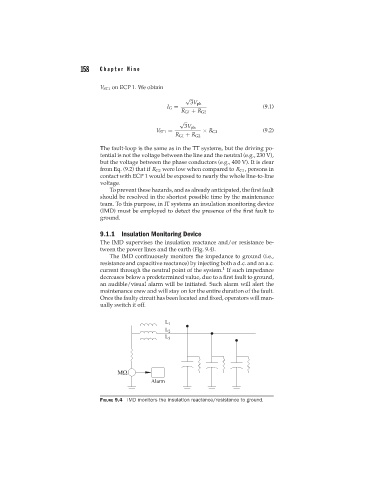
9.1.1 Insulation Monitoring Device
The IMD supervises the insulation reactance and/or resistance be-
tween the power lines and the earth (Fig. 9.4).
The IMD continuously monitors the impedance to ground (i.e.,
resistance and capacitive reactance) by injecting both a d.c. and an a.c.
1
current through the neutral point of the system. If such impedance
decreases below a predetermined value, due to a first fault to ground,
an audible/visual alarm will be initiated. Such alarm will alert the
maintenance crew and will stay on for the entire duration of the fault.
Once the faulty circuit has been located and fixed, operators will man-
ually switch it off.
FIGURE 9.4 IMD monitors the insulation reactance/resistance to ground.