
Page 179 - Electrical Safety of Low Voltage Systems
P. 179
162 Chapter Nine
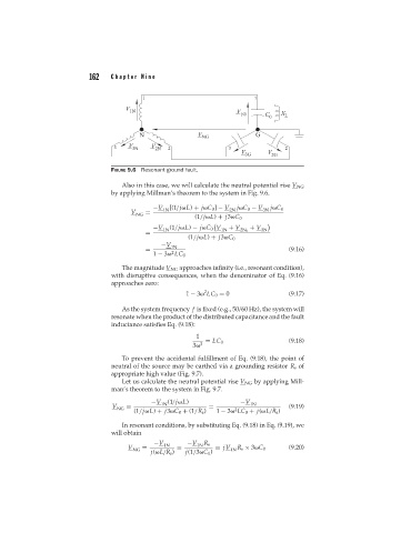
FIGURE 9.6 Resonant ground fault.
Also in this case, we will calculate the neutral potential rise V NG
by applying Millman’s theorem to the system in Fig. 9.6.
−V 1N [(1/j L) + j C 0 ] − V 2N j C 0 − V 3N j C 0
V =
NG
(1/j L) + j3 C 0
−V 1N (1/j L) − j C 0 V 1N + V + V 3N
= 2N 0
(1/j L) + j3 C 0
−V 1N
= (9.16)
2
1 − 3 LC 0
The magnitude V NG approaches infinity (i.e., resonant condition),
with disruptive consequences, when the denominator of Eq. (9.16)
approaches zero:
2
1 − 3 LC 0 = 0 (9.17)
As the system frequency f is fixed (e.g., 50/60 Hz), the system will
resonate when the product of the distributed capacitance and the fault
inductance satisfies Eq. (9.18):
1
= LC 0 (9.18)
2
3
To prevent the accidental fulfillment of Eq. (9.18), the point of
neutral of the source may be earthed via a grounding resistor R s of
appropriate high value (Fig. 9.7).
Let us calculate the neutral potential rise V NG by applying Mill-
man’s theorem to the system in Fig. 9.7.
−V 1N (1/j L) −V 1N
V NG = = (9.19)
2
(1/j L) + j3 C 0 + (1/R s ) 1 − 3 LC 0 + j( L/R s )
In resonant conditions, by substituting Eq. (9.18) in Eq. (9.19), we
will obtain
−V 1N −V 1N R s
V NG = = = jV 1N R s × 3 C 0 (9.20)
j( L/R s ) j(1/3 C 0 )