
Page 176 - Electrical Safety of Low Voltage Systems
P. 176
IT Grounding System 159
A simpler method of ground-fault detection consists of three
lamps connected between each line and the earth. At the occurrence of
a ground fault, there will be a reduction in the voltage across the lamp
linked to the faulted phase, which therefore will dim, while the others
will become brighter.
9.1.2 Equipotential Bonding
In IT systems, the equipotential bonding, consisting of connections
between enclosures of fixed equipment and EXCPs, when simulta-
neously accessible, add safety to the installation. The equipotential
bonding should also connect, if practicable, the metal frame of the
building or the reinforced bars embedded in the structure’s concrete.
The resulting equipotential system converging to the main
grounding bus should “generate” from there all the protective con-
ductors, including, of course, those to receptacles.
The criterion to assess the safety of the bonding connection be-
tween ECPs and EXCPs is based on the resistance of the connection
itself, as follows:
R B I a ≤ 50 V (9.3)
where R B is the resistance of the bonding connection and I a is the
operating current of the protective device in correspondence with the
maximum disconnection time as per Table 6.1 or Table 7.1, according
to the way the ECPs are earthed, singularly or collectively, as further
explained in Sec. 9.5.
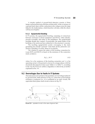
9.2 Overvoltages Due to Faults in IT Systems
The main issue in IT systems is the possibility of overvoltages induced
by ground faults. With reference to Fig. 9.2, where the system leakage
resistance is neglected (i.e., it is considered as an open circuit), the
equivalent three-phase fault circuit is shown in Fig. 9.5.
FIGURE 9.5 Equivalent circuit in the case of ground fault.