
Page 185 - Electrical Safety of Low Voltage Systems
P. 185
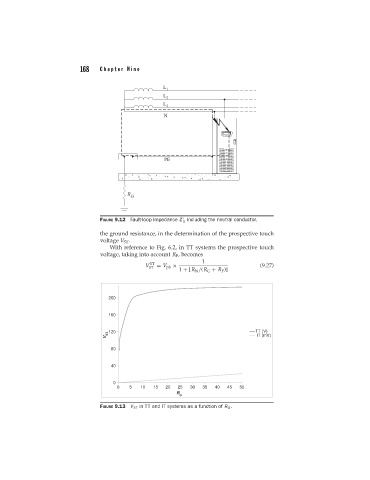
168   Chapter Nine


                                  FIGURE 9.12 Fault-loop impedance Z including the neutral conductor.
                                                             S
                                  the ground resistance, in the determination of the prospective touch
                                  voltage V ST .
                                     With reference to Fig. 6.2, in TT systems the prospective touch
                                  voltage, taking into account R F , becomes
                                                                    1
                                                   TT
                                                 V   = V ph ×                          (9.27)
                                                  ST
                                                            1 + [R N /(R G + R F )]


                                     200


                                     160

                                    V ST  120                                        TT (V)
                                                                                      IT (mV)

                                      80

                                      40


                                      0
                                        0   5  10   15  20  25  30  35  40  45  50
                                                           R
                                                            G
                                  FIGURE 9.13 V ST in TT and IT systems as a function of R G .