
Page 186 - Electrical Safety of Low Voltage Systems
P. 186
IT Grounding System 169
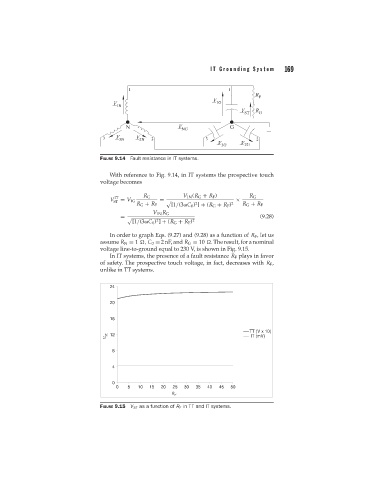
FIGURE 9.14 Fault resistance in IT systems.
With reference to Fig. 9.14, in IT systems the prospective touch
voltage becomes
V IT R G V 1N (R G + R F ) × R G
ST = V 1G = 2 2
R G + R F [1/(3 C 0 ) ] + (R G + R F ) R G + R F
V 1N R G
(9.28)
=
2
[1/(3 C 0 ) ] + (R G + R F ) 2
In order to graph Eqs. (9.27) and (9.28) as a function of R F , let us
assume R N = 1 , C 0 = 2 nF, and R G = 10 . The result, for a nominal
voltage line-to-ground equal to 230 V, is shown in Fig. 9.15.
In IT systems, the presence of a fault resistance R F plays in favor
of safety. The prospective touch voltage, in fact, decreases with R F ,
unlike in TT systems.
24
20
16
TT (V x 10)
V ST 12 IT (mV)
8
4
0
0 5 10 15 20 25 30 35 40 45 50
R F
FIGURE 9.15 V ST as a function of R F in TT and IT systems.