
Page 193 - Electrical Safety of Low Voltage Systems
P. 193
176 Chapter Te n
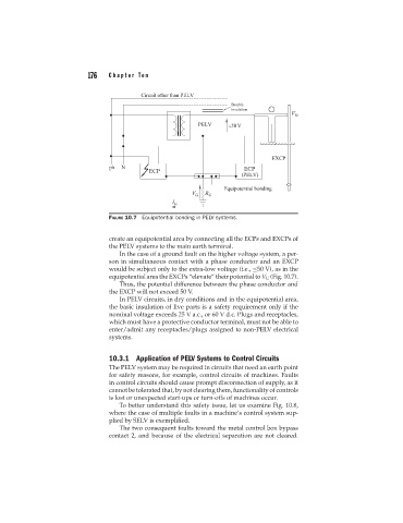
FIGURE 10.7 Equipotential bonding in PELV systems.
create an equipotential area by connecting all the ECPs and EXCPs of
the PELV systems to the main earth terminal.
In the case of a ground fault on the higher voltage system, a per-
son in simultaneous contact with a phase conductor and an EXCP
would be subject only to the extra-low voltage (i.e., ≤50 V), as in the
equipotential area the EXCPs “elevate” their potential to V G (Fig. 10.7).
Thus, the potential difference between the phase conductor and
the EXCP will not exceed 50 V.
In PELV circuits, in dry conditions and in the equipotential area,
the basic insulation of live parts is a safety requirement only if the
nominal voltage exceeds 25 V a.c., or 60 V d.c. Plugs and receptacles,
which must have a protective conductor terminal, must not be able to
enter/admit any receptacles/plugs assigned to non-PELV electrical
systems.
10.3.1 Application of PELV Systems to Control Circuits
The PELV system may be required in circuits that need an earth point
for safety reasons, for example, control circuits of machines. Faults
in control circuits should cause prompt disconnection of supply, as it
cannot be tolerated that, by not clearing them, functionality of controls
is lost or unexpected start-ups or turn-offs of machines occur.
To better understand this safety issue, let us examine Fig. 10.8,
where the case of multiple faults in a machine’s control system sup-
plied by SELV is exemplified.
The two consequent faults toward the metal control box bypass
contact 2, and because of the electrical separation are not cleared.